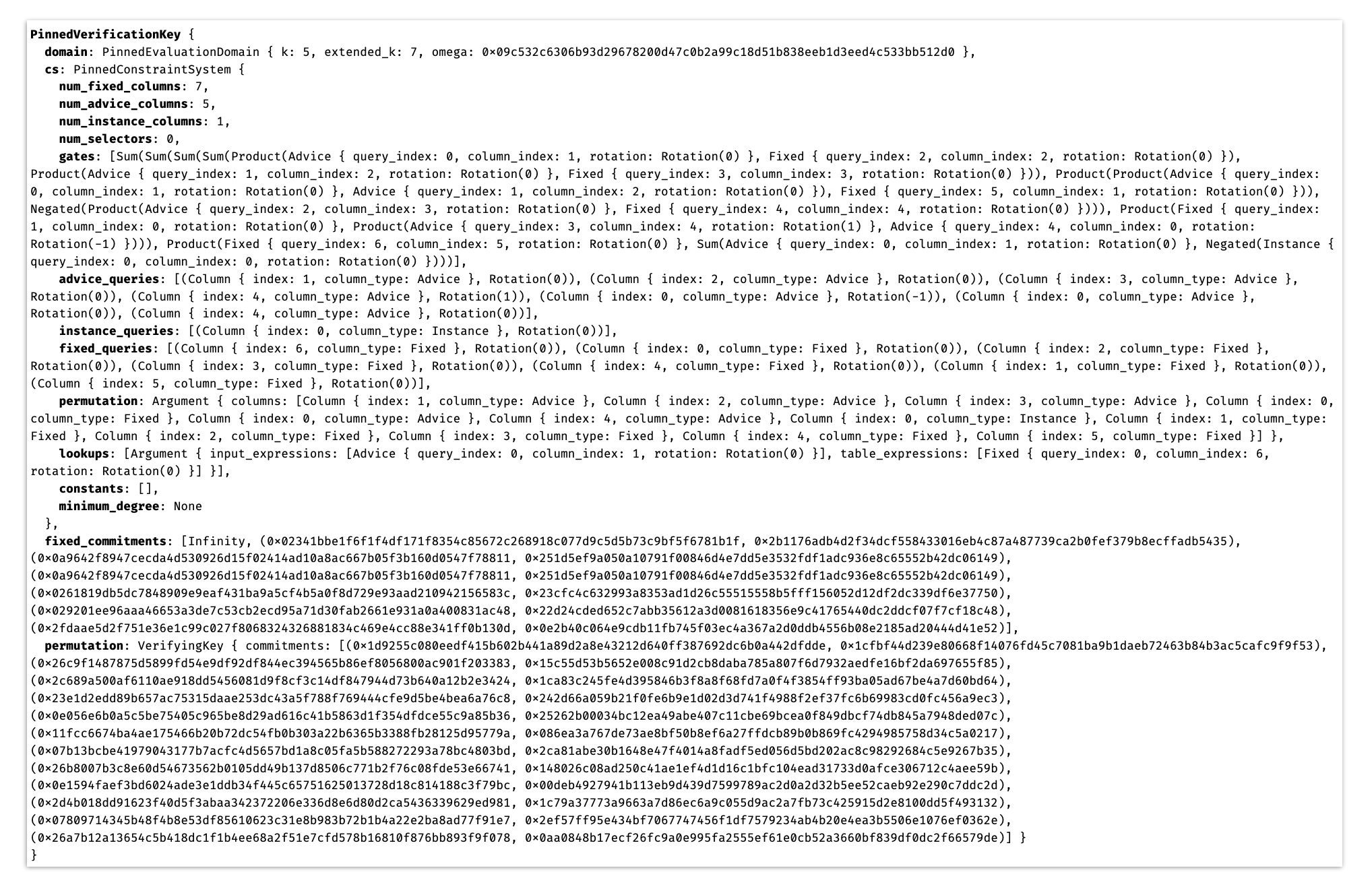
On March 3rd, 2025, zkSecurity was tasked to audit the Midnight Halo2 fork. The specific code to review was shared via GitHub as a public repository (https://github.com/midnightntwrk/halo2 at commit 417f29a5c0ede5d98825b95c8e8e9a1532ec177c). The audit was conducted between March 3rd, 2025 and March 28th, 2025 by two consultants. The audit focused on the correctness and security of the generalized Plonk implementation as well as circuit framework in the Midnight fork.
The code was found to be clean and well organized. Several observations and findings have been reported to the Midnight team, which are detailed in the following sections.
The scope of this audit is the whole Midnight Halo2 framework, which is forked from PSE Halo2. The differences between the main Halo2 forks are described below.
Halo2 is a zero-knowledge proof system that implements the ideas developed by the team behind the Electric Coin Company’s (ECC) Zcash. The current open source system is a result of various iterations of the system, starting with efforts in 2019 (original Halo and its related publication). The resulting current Halo2 is a zk-SNARK system based on PLONK but several enhancements to allow for more general, custom gates and lookups. It also allows recursive proofs and does not need a per-circuit trusted setup, but instead relies on a one-time universal setup. It is a popular proof system that is used beyond Zcash: at the time of writing this report (March 2025), it has over 500 forks and over 700 projects use it. It has seen over 30 contributors and closed over 400 pull requests. Halo2 powers the Zcash Orchard protocol since 2022.
The most popular Halo2 fork is the one from the PSE (Privacy and Scaling Explorations) group at the Ethereum Foundation. This fork is tailored for Ethereum-oriented use cases involving on-chain verification. Therefore, it focuses on the BN254 curve and KZG commitments, instead of the original “Halo” style using Pasta curves. This is because BN254 offers a convenient precompile on Ethereum mainnet, making on-chain verification cheaper. KZG commitments over BN254 are standard in many Ethereum-based ZK rollups. This fork also implements a re-architecture of the original codebase, splitting frontend and backend. PSE merges many upstream changes from the ECC code, but diverges on some features, for instance those related to EVM compatibility.
In this report we audit the Midnight fork of the PSE fork. The main differences with respect to the PSE fork are as follows. First, a number of unused features were removed, such as compressed selectors, IPA and the use of SHPLONK for proof aggregation. Moreover the interfaces of KZG and polynomial commitment scheme were rewritten. Finally, a configuration feature was added to allow for truncated challenges, used mainly during KZG. Such a truncation aims at improving efficiency while preserving security.
Two key interfaces at the front-end, Circuit::configure and Circuit::synthesize, give developers flexibility in composing circuits while encapsulating most of the low-level complexity.
Circuit::configure is used to define gate constraints. It provides access to the ConstraintSystem API, through which developers specify constraint expressions. Below is an example of defining a multiplication gate constraint:
fn configure(
    meta: &mut ConstraintSystem<F>
) -> <Self as Chip<F>>::Config {
    // We create the two advice columns that FieldChip uses for I/O.
    let advice = [meta.advice_column(), meta.advice_column()];

    // We also need an instance column to store public inputs.
    let instance = meta.instance_column();

    // Create a fixed column to load constants.
    let constant = meta.fixed_column();

    meta.enable_equality(instance);
    meta.enable_constant(constant);
    for column in &advice {
        meta.enable_equality(*column);
    }
    let s_mul = meta.selector();

    // Define our multiplication gate
    meta.create_gate("mul", |meta| {
        let lhs = meta.query_advice(advice[0], Rotation::cur());
        let rhs = meta.query_advice(advice[1], Rotation::cur());
        let out = meta.query_advice(advice[0], Rotation::next());
        let s_mul = meta.query_selector(s_mul);

        vec![s_mul * (lhs * rhs - out)]
    });

    FieldConfig {
        advice,
        instance,
        s_mul,
    }
}
Developers can create new columns (advice, instance, and fixed). Advice columns store runtime witness values, instance columns store public inputs, and fixed columns hold compile-time constants. Each of these columns may be “equality-enabled” to participate in copy constraints.
enable_equality/enable_constant
To avoid unnecessary overhead in the permutation argument, developers must manually enable equality for columns that will be involved in copy constraints or equality checks. Notice that the constant column is not directly constrained in this gate, but we enable equality on it to allow constraining a cell to a constant value later.
Selector
A selector expression is a virtual column, which is not materialized like the columns until key generation phase. In vanilla Plonk, there are simple and complex selectors. Simple selectors only allow to be applied to entire gate constraints (e.g., q * (A * B - C)), while complex selectors can appear inside expressions (e.g., A * B - q * C).
In this midnight fork, the simple selector is unnecessary, as it does not use selector-combining optimizations. Ultimately, the selector expression is turned into a fixed-column value during key generation.
create_gate
ConstraintSystem::create_gate defines a gate constraint. In the snippet above, lhs, rhs, and out are queries referencing specific columns and rotations, while s_mul is the selector expression that eventually becomes a fixed column. The multiplication gate is enforced by the polynomial expression:
s_mul * (lhs * rhs - out)
The expression’s internal data structure looks like:
[
    Product(
        Selector(
            Selector(0, true)
        ),
        Sum(
            Product(
                Advice { query_index: 0, column_index: 0, rotation: Rotation(0) },
                Advice { query_index: 1, column_index: 1, rotation: Rotation(0) }
            ),
            Negated(Advice { query_index: 2, column_index: 0, rotation: Rotation(1) })
        )
    )
]
In this case, Advice and Selector are the lowest level expressions, while the others like Product, Sum and Negated are composable expressions. By providing the evaluations for the lowest level expressions, a composed expression can be evaluated recursively.
During proving, this structure represents a gate constraint polynomial in the vanishing polynomial evaluation. The query_index indicates how the verifier loads the corresponding cell evaluation from the transcript, as in:
// load evals from transcript
let advice_evals = (0..num_proofs)
    .map(|_| -> Result<Vec<_>, _> { read_n(transcript, vk.cs.advice_queries.len()) })
    .collect::<Result<Vec<_>, _>>()?;

let fixed_evals = read_n(transcript, vk.cs.fixed_queries.len())?;

// load an eval based on query index embedded in expression
gate.polynomials().iter().map(move |poly| {
    poly.evaluate(
        &|query| fixed_evals[query.index.unwrap()],
        &|query| advice_evals[query.index.unwrap()],

..TRUNCATED
Circuit::synthesize is responsible for circuit construction. It provides the Layouter API, which lets developers build regions and wire cells. Below is an example of synthesizing the multiplication gate:
fn mul(
    &self,
    mut layouter: impl Layouter<F>,
    a: AssignedCell,
    b: AssignedCell,
) -> Result<AssignedCell, Error> {
    let config = self.config();

    layouter.assign_region(
        || "mul",
        |mut region: Region<'_, F>| {
            config.s_mul.enable(&mut region, 0)?;

            a.0.copy_advice(|| "lhs", &mut region, config.advice[0], 0)?;
            b.0.copy_advice(|| "rhs", &mut region, config.advice[1], 0)?;

            let value = a.0.value().copied() * b.0.value();

            region
                .assign_advice(|| "lhs * rhs", config.advice[0], 1, || value)
                .map(Number)
        },
    )
}
A region is a consecutive set of rows in which constraints can be applied. The assign_region method specifies the logic for that region, including copy constraints, gate constraints and witness generation. Selectors are enabled by referencing a region and a specific row in that region.
Copy Constraint
The copy_advice method can wire cells from anywhere in the circuit, include the cells from the other regions. Internally, it updates the permutation mapping using the cells’ column indices and row offsets:
fn constrain_equal(&mut self, left: Cell, right: Cell) -> Result<(), Error> {
    self.plan.cs.copy(
        left.column,
        *self.plan.regions[*left.region_index] + left.row_offset,
        right.column,
        *self.plan.regions[*right.region_index] + right.row_offset,
    )?;

    Ok(())
}
Here, the actual row offset is calculated from the region index stored within each cell.
Witness Generation
The value method returns the cell’s value for witness generation. In practice, witness generation and circuit construction are separate. The Assignment trait enables this separation:
-
During proving, WitnessCollection implements Assignment to gather witness values.
-
Assembly handles fixed values (constants, permutation mappings, static lookup tables) for key generation, where these values must be committed.
Constraint Constants
The earlier configure example does not explicitly use the constant column inside create_gate, but it may still be necessary. Whenever a cell must be constrained to a constant value, that constant is first assigned to a constant (fixed) column, then a copy constraint is applied from the constant cell to the advice cell. The front-end provides assign_advice_from_constant for this:
fn assign_advice_from_constant<'v>(
    &'v mut self,
    annotation: &'v (dyn Fn() -> String + 'v),
    column: Column<Advice>,
    offset: usize,
    constant: Rational<F>,
) -> Result<Cell, Error> {
    let advice =
        self.assign_advice(annotation, column, offset, &mut || Value::known(constant))?;
    self.constrain_constant(advice, constant)?;

    Ok(advice)
}
Behind the scenes, the tuple (cell, constant) recorded by constrain_constant is used to create a copy constraint from the constant cell to the advice cell via ConstraintSystem::assign_fixed and ConstraintSystem::copy:
for (constant, advice) in constants_to_assign {
    self.cs.assign_fixed(
        || format!("Constant({:?})", constant.evaluate()),
        constants_column,
        *next_constant_row,
        || Value::known(constant),
    )?;
    self.cs.copy(
        constants_column.into(),
        *next_constant_row,
        advice.column,
        *self.regions[*advice.region_index] + advice.row_offset,
    )?;
    *next_constant_row += 1;
}
Materialize Selectors
Each virtual selector must be converted to a fixed column before computing commitments during key generation. The replace_selectors_with_fixed method accomplishes this:
pub fn directly_convert_selectors_to_fixed(
    mut self,
    selectors: Vec<Vec<bool>>,
) -> (Self, Vec<Vec<F>>) {
    // The number of provided selector assignments must be the number we
    // counted for this constraint system.
    assert_eq!(selectors.len(), self.num_selectors);

    let (polys, selector_replacements): (Vec<_>, Vec<_>) = selectors
        .into_iter()
        .map(|selector| {
            let poly = selector
                .iter()
                .map(|b| if *b { F::ONE } else { F::ZERO })
                .collect::<Vec<_>>();
            let column = self.fixed_column();
            let rotation = Rotation::cur();
            let expr = Expression::Fixed(FixedQuery {
                index: Some(self.query_fixed_index(column, rotation)),
                column_index: column.index,
                rotation,
            });
            (poly, expr)
        })
        .unzip();

    self.replace_selectors_with_fixed(&selector_replacements);
    self.num_selectors = 0;

    (self, polys)
}
In the process, the selector expressions are converted to fixed column expressions, and the number of selectors is reset to zero. After this, the commitments to the selectors can be computed directly from the fixed column values.
Given a circuit, Halo2 will call the Circuit::synthesize function to layout the circuit and assign the cells during key generation and proving time. Halo2 uses three key traits from top-down to manage the layout and assignment: Layouter, RegionLayouter, and Assignment. To assign a cell in the circuit, Halo2 typically calls these traits top-down:
–> Circuit.synthesize
–-> Layouter.assign_region
–--> RegionLayouter.assign_advice
–---> Assignment.assign_advice
Layouter Trait is responsible for managing and laying out all regions. You can imagine each region to be a rectangle with different width and height. The layouter needs to arrange these regions (with no overlap) in a big table. For efficiency reasons, the big table should have as few rows as possible.
NamespacedLayouter in src/circuit/mod.rs: this layouter is used for debugging. It keeps the current namespace string and wraps other layouters.SingleChipLayouter in src/circuit/floor_planner/single_pass.rs: this is the simplest layouter strategy. It just aligns regions by the given order. The current region is placed at the first available row.V1Pass in src/circuit/floor_planner/v1.rs: it lays out the region using a greedy strategy. It sorts the regions by area (num_advice_column * num_row) in descending order. It places regions from largest to smallest. When placing the current region, it will try to find if there is a gap (that is large enough to fit the current region) among previous regions. If so, it places the current region in the gap; otherwise, it places the region in the first available row.
RegionLayouter Trait is for tracking states inside one region.
RegionShape in src/circuit/layouter.rs: it tracks the number of rows in the region, considering only the row count and ignoring the assigned values.SingleChipLayouterRegion in src/circuit/floor_planner/single_pass.rs: it’s the region layouter for SimpleFloorPlanner layouter.V1Region for src/circuit/floor_planner/v1.rs: it’s the region layouter for V1 layouter.
The main difference between SingleChipLayouterRegion and V1Region is how they handle constants.
Assignment Trait is for tracking the assignment of cells in Advice column and Fixed column
Assembly in src/plonk/keygen.rs: for tracking fixed column values (including selector) and the copy constraint (for permutation). The assignment in advice column is ignored. This is used to generate verifying key, including fixed column commitment and permutation commitment.WitnessCollection in src/plonk/prover.rs: for the prover to collect witness (i.e., the value in the advice columns). This is used in proving time.
Key generation is the process of generating the proving key and the verifying key. The verifying key is constructed from the circuit and contains information about the circuit as well as commitments to public columns. The proving key contains the verifying key along with auxiliary polynomials necessary for creating zero-knowledge proofs. Simply put, key generation converts the representation of the circuit from a large table to a set of polynomials evaluated in the extended domain, which can then be used in the backend to either create or verify a proof.
/// This is a verifying key which allows for the verification of proofs for a
/// particular circuit.
#[derive(Clone, Debug)]
pub struct VerifyingKey<F: PrimeField, CS: PolynomialCommitmentScheme<F>> {
    domain: EvaluationDomain<F>,
    fixed_commitments: Vec<CS::Commitment>,
    permutation: permutation::VerifyingKey<F, CS>,
    cs: ConstraintSystem<F>,
    cs_degree: usize,
    transcript_repr: F,
}

/// NOTE: permutation::VerifyingKey
/// The verifying key for a single permutation argument.
#[derive(Clone, Debug)]
pub struct VerifyingKey<F: PrimeField, CS: PolynomialCommitmentScheme<F>> {
    commitments: Vec<CS::Commitment>,
}
The first step in constructing a verifying key is to set a value k, where 2^k corresponds to the number of rows in the final table. This value can be set automatically by calling keygen_vk with a ConcreteCircuit instance and PolynomialCommitmentScheme::Parameters, or the caller can specify a value using keygen_vk_with_k. Note that 2^k should be large enough to accommodate the rows required by the circuit as well as the blinding factors.
The second step is to synthesize the circuit. This is done by calling ConcreteCircuit::FloorPlanner::synthesize, which, by default, invokes the synthesize method on the circuit. As detailed in our overview of the Frontend APIs, the synthesize method constructs the circuit by building regions and wire constraints. At this point, if the specified 2^k value is not large enough to accommodate the circuit, a NotEnoughRowsAvailable error will be thrown.
The next step is to merge the selector polynomials with the fixed polynomials by converting the boolean values of the selectors to field elements (0 or 1) and appending them to the fixed polynomials. Each of these polynomials is then committed using the commit_lagrange method of the polynomial commitment scheme, which performs Multi-Scalar Multiplication (MSM) with the Structured Reference String (SRS) of the KZG commitment scheme.
Finally, we build the verifying key for the permutation argument, which consists of commitments to the permutation polynomials. As outlined in the Halo2 book, the cells of the permutation columns are populated by permuted indices, where the index is defined by for the i-th row and the j-th column.
/// This is a proving key which allows for the creation of proofs for a
/// particular circuit.
#[derive(Clone, Debug)]
pub struct ProvingKey<F: PrimeField, CS: PolynomialCommitmentScheme<F>> {
    vk: VerifyingKey<F, CS>,
    l0: Polynomial<F, ExtendedLagrangeCoeff>,
    l_last: Polynomial<F, ExtendedLagrangeCoeff>,
    l_active_row: Polynomial<F, ExtendedLagrangeCoeff>,
    fixed_values: Vec<Polynomial<F, LagrangeCoeff>>,
    fixed_polys: Vec<Polynomial<F, Coeff>>,
    fixed_cosets: Vec<Polynomial<F, ExtendedLagrangeCoeff>>,
    permutation: permutation::ProvingKey<F>,
    ev: Evaluator<F>,
}

/// NOTE: permutation::ProvingKey
/// The proving key for a single permutation argument.
#[derive(Clone, Debug)]
pub(crate) struct ProvingKey<F: PrimeField> {
    permutations: Vec<Polynomial<F, LagrangeCoeff>>,
    polys: Vec<Polynomial<F, Coeff>>,
    pub(super) cosets: Vec<Polynomial<F, ExtendedLagrangeCoeff>>,
}
The implementation of proving key generation is similar to verifying key generation, with some key differences:
-
The proving key generation takes a VerifyingKey as an argument, meaning it is not possible to set a custom k value.
-
Instead of creating commitments to the fixed and permutation polynomials, the proving key generation interpolates them to obtain their coefficients and evaluates them in the extended domain.
-
The proving key generation computes selector polynomials for the blinding factors, namely l_0(X), l_last(X), and l_active_row(X). See this section for more details.
-
The proving key also creates an Evaluator for the circuit, which generates an optimized data structure for evaluating the circuit.
Some important notes about how the polynomials are represented in the proving key:
-
The polynomials are represented as Lagrange polynomial evaluations, which speeds up the computation of addition and multiplication over polynomials compared to using coefficient form.
-
The polynomials are “blown up” to a larger degree to account for the increased degree of the resulting polynomial from the multiplication of the selector polynomials.
-
The polynomials are not evaluated in the blown-up multiplicative group but rather in the coset of the blown-up multiplicative group. In the case of Halo2, this is achieved by evaluating the polynomials at instead of , where is a cube root of unity. Refer to this outline for more details on why this is necessary.
The proof system used in this protocol is very similar to the original Halo2 proving system. The most notable difference is that this protocol uses KZG as the polynomial commitment scheme instead of the Inner Product Argument (IPA) used in the original Halo2 protocol.
Throughout the protocol, the commitment of a polynomial is denoted by , which represents the KZG commitment of . This is computed by performing Multi-Scalar Multiplication (MSM) on the coefficients of as scalars against structured group elements , which are generated during a trusted setup using the secret .
At a high level, the Halo2 proof system consists of the following interactions between the prover and the verifier.
At the start of the protocol, the prover possesses a table of cell assignments that satisfy the constraint system. This table consists of rows, divided into:
- Fixed columns denoted by
- Advice and instance columns denoted by
where corresponds to the -th row and -th column.
Prover: Commits and to the verifier:
- as purported commitment of
- as purported commitment of
where and are Lagrange polynomials interpolating such that:
Verifier: The verifier receives and , then samples a random challenge
Prover: Given a lookup with input column polynomials and table column polynomials for all in rows, the prover calculate the following to compress the polynomials using :
The prover then permutes these compressed polynomials, obtaining and , according to the lookup argument.
The prover commits to the verifier.
Verifier: The verifier receives and samples random challenges and .
Prover: The prover constructs and as equality constraint permutation polynomial and lookup permutation product polynomial respectively, according to the permutation argument and lookup argument.
Then, the prover commits these polynomials:
-
-
After all circuit commitments are committed, the protocol will perform vanishing argument to ensure the satisfiability of circuit relations.
Vanishing argument is the protocol to demonstrate that the Halo2 circuit relations are satisfied, specifically it satisfies all the gates and custom gates, lookup arguments, and the equality constraint permutations.
Prover: The prover commit random polynomial for degree for blinding.
Verifier: The verifier samples a random challenge .
Prover: The prover construct the following polynomial:
where is polynomial representing the gate in the circuit (which can include polynomial and as well), and is vanishing polynomial . If the numerator polynomial is perfectly divisible by , then the circuit relations are satisfied with high probability.
Then, the prover split the polynomial into pieces of smaller-degree polynomial:
The prover commits to the verifier.
Verifier: Receives commitment and samples a random challenge .
Prover: The prover evaluates all polynomials that have been committed so far, using evaluation point (this includes polynomial ). Then, the prover send all these evaluations to the verifier.
Verifier: The verifier receives all the evaluations and check that these evaluations satisfy the form of :
If the above check is satisfied, then the verifier can conclude that the circuit relations are satisfied. However, the verifier needs one remaining check that the evaluations themselves are consistent with the original commitments that have been made throughout the protocol. This check is done by the multipoint opening argument below.
At the end of Halo2 verification, the verifier has KZG commitments of multiple polynomials and wants to evaluate them at different points. The naive way is to evaluate each polynomial and each point one-by-one. That is apparently not efficient enough. We would like to evaluate them in one batch to reduce the proof size and the computation.
Let’s say given committed function , , , and . We want to evaluate and on point , evaluate and on and , where denotes the root of unity of the evaluation domain. The general idea is to evaluate and in a batch, and in another batch, and verify them together.
Below are some functions defined in the protocol. We put them here just for convenient reference. , , , and are random elements sampled by the verifier. Define as random linear combination of and , as random linear combination of and :
Define as the vanishing polynomial . The same for . is the interpolated polynomial such that . Same, is the interpolated polynomial such that and . Then we have the quotient polynomial for and :
Define as the random linear combination of and :
Define as the random linear combination of , and :
Prover:
Send the KZG commitment of the polynomial , , and . Send the purported evaluation values , , , , , and .
Verifier:
The verifier would like to batch and , and . It samples a random element to combine the commitment:
Note that the verifier can compute the evaluation of at , and :
Further, the verifier samples a random element to combine q_1 and q_2.
Prover:
Compute
Commit the function to .
Verifier:
Receive the purported . The verifier needs to check if is correct. It would like to check the commitment at a random point. Therefore it samples and wants to check if
However, the Verifier cannot evaluate and on its own. Instead, it asks the prover for help.
Prover:
Calculate and . Send these values to the Verifier.
Verifier:
Receive the purported and . The verifier needs to check if these values are correct.
Now it can compute the value :
Now the Verifier has two things to check:
- Check the value against the purported commitment .
- Check the purported and values against the commitment and .
Again, sample a random number and batch these checks together. Sample and apply linear combinator to these checks.
Combine the commitment: .
Combine the evaluate value:
The last thing to do is to check against .
Prover:
Create the KZG openings that shows :
Verifier:
Verify that using . If that check passes, it means that the purported and values are consistent with and . This means that the value is consistent with the commitment . Then it means is indeed the commitment of the combined quotient polynomial. Finally this means that these evaluations (, , , , , and ) are correct.
In this section we explain how blinding works to turn the protocol zero-knowledge.
Every witness column is sent as a commitment as part of the protocol. Due to this, information leakage can happen due to two reasons:
- An attacker can produce many witness values and commit to them to see if they match the committed witness (as KZG is implemented without hiding).
- Each evaluation of a committed polynomial can leak information on the polynomial itself (and with enough evaluations a polynomial and the column it represents can be reconstructed).
To tackle both issues, witness columns are randomized with blinding factors. That is, some of the rows are filled with randomly generated field elements.
We know that we need at least as many blinding factors as evaluations to perfectly blind each of the prover’s witness columns.
The number of blinding factors is documented as part of the blinding_factors function which tries to account for all the evaluations in the protocol:
impl<F: Field> ConstraintSystem<F> {
    /// Compute the number of blinding factors necessary to perfectly blind
    /// each of the prover's witness polynomials.
    pub fn blinding_factors(&self) -> usize {
        // All of the prover's advice columns are evaluated at no more than
        let factors = *self.num_advice_queries.iter().max().unwrap_or(&1);
        // distinct points during gate checks.

        // - The permutation argument witness polynomials are evaluated at most 3 times.
        // - Each lookup argument has independent witness polynomials, and they are
        //   evaluated at most 2 times.
        let factors = std::cmp::max(3, factors);

        // Each polynomial is evaluated at most an additional time during
        // multiopen (at x_3 to produce q_evals):
        let factors = factors + 1;

        // h(x) is derived by the other evaluations so it does not reveal
        // anything; in fact it does not even appear in the proof.

        // h(x_3) is also not revealed; the verifier only learns a single
        // evaluation of a polynomial in x_1 which has h(x_3) and another random
        // polynomial evaluated at x_3 as coefficients -- this random polynomial
        // is "random_poly" in the vanishing argument.

        // Add an additional blinding factor as a slight defense against
        // off-by-one errors.
        factors + 1
    }
As shown above, the calculation accounts not only for the evaluations that appear as part of the constraints, but also:
- An additional evaluation at is accounted which we talk about in the Multipoint Opening Overview section.
- An additional blinding factor is added as a slight defense against off-by-one errors. We think this is a great idea as the slightest mistake here might lead to zero-knowledge issues.
The calculated number of blinding factors is later used in the protocol for the prover to blind each of the advice columns. In src/plonk/prover.rs:
let unusable_rows_start = domain.n as usize - (meta.blinding_factors() + 1);
for current_phase in pk.vk.cs.phases() {
    // TRUNCATED...
    for ((circuit, advice), instances) in circuits.iter().zip(advice.iter_mut()).zip(instances) {
        let mut witness = WitnessCollection {
            k: domain.k(),
            current_phase,
            advice: vec![domain.empty_lagrange_rational(); meta.num_advice_columns],
            unblinded_advice: HashSet::from_iter(meta.unblinded_advice_columns.clone()),
            instances,
            challenges: &challenges,
            // The prover will not be allowed to assign values to advice
            // cells that exist within inactive rows, which include some
            // number of blinding factors and an extra row for use in the
            // permutation argument.
            usable_rows: ..unusable_rows_start,
            _marker: std::marker::PhantomData,
        };

        // TRUNCATED...

        for (column_index, advice_values) in column_indices.iter().zip(&mut advice_values) {
            if !witness.unblinded_advice.contains(column_index) {
                for cell in &mut advice_values[unusable_rows_start..] {
                    *cell = F::random(&mut rng);
                }
Note that usable_rows are smaller than expected, as one row is reserved for the final value of permutation accumulators (see next subsection). As such, advice columns actually have an extra blinding factor added to them.
The permutation argument introduces extra polynomials, which can be seen as adding and using extra columns in the protocol. As these columns also get evaluated as well, they reuse the blinding factors computation from the previous section which accounted for 3 evaluations at , and . The last evaluation is new (compared to the vanilla Plonk protocol) due to the chunking of the accumulator over several columns to extend the permutation to more than just three advice columns.
Due to the blinding, an extra row must be reserved to store the final value of the accumulator (which is normally stored in the very first row in the vanilla Plonk protocol, due to the absence of blinding factors which allow for wrapping around).
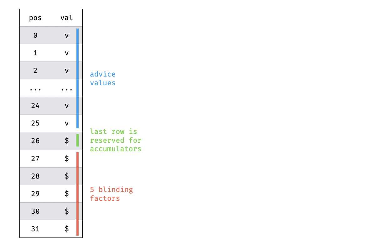
We have verified that this last row is correctly accounted in other parts of the protocol. This is important because no lookup or custom gate constraints can be applied there.
You can see the blinding of these polynomials implemented in src/plonk/permutation/prover.rs:
impl Argument {
    #[allow(clippy::too_many_arguments)]
    pub(in crate::plonk) fn commit<
        F: WithSmallOrderMulGroup<3>,
        CS: PolynomialCommitmentScheme<F>,
        R: RngCore,
        T: Transcript,
    >(
        &self,
        params: &CS::Parameters,
        pk: &plonk::ProvingKey<F, CS>,
        pkey: &ProvingKey<F>,
        advice: &[Polynomial<F, LagrangeCoeff>],
        fixed: &[Polynomial<F, LagrangeCoeff>],
        instance: &[Polynomial<F, LagrangeCoeff>],
        beta: F,
        gamma: F,
        mut rng: R,
        transcript: &mut T,
    ) -> Result<Committed<F>, Error>
    where
        CS::Commitment: Hashable<T::Hash>,
    {
        let domain = &pk.vk.domain;

        // How many columns can be included in a single permutation polynomial?
        // We need to multiply by z(X) and (1 - (l_last(X) + l_blind(X))). This
        // will never underflow because of the requirement of at least a degree
        // 3 circuit for the permutation argument.
        assert!(pk.vk.cs_degree >= 3);
        let chunk_len = pk.vk.cs_degree - 2;
        let blinding_factors = pk.vk.cs.blinding_factors();

        // TRUNCATED...

        for (columns, permutations) in self
            .columns
            .chunks(chunk_len)
            .zip(pkey.permutations.chunks(chunk_len))
        {

            // TRUNCATED...

            // Set blinding factors
            for z in &mut z[domain.n as usize - blinding_factors..] {
                *z = F::random(&mut rng);
            }
            // Set new last_z
            last_z = z[domain.n as usize - (blinding_factors + 1)];
The lookup uses three new columns: a permutation column that reuses the same blinded layout as the above polynomials:
impl<F: WithSmallOrderMulGroup<3>> Permuted<F> {
    pub(in crate::plonk) fn commit_product<CS: PolynomialCommitmentScheme<F>, T: Transcript>(
        self,
        pk: &ProvingKey<F, CS>,
        params: &CS::Parameters,
        beta: F,
        gamma: F,
        mut rng: impl RngCore + CryptoRng,
        transcript: &mut T,
    ) -> Result<Committed<F>, Error>
    where
        F: WithSmallOrderMulGroup<3> + FromUniformBytes<64>,
        CS::Commitment: Hashable<T::Hash>,
    {
        let blinding_factors = pk.vk.cs.blinding_factors();

        // TRUNCATED...

        let z = iter::once(F::ONE)
            .chain(lookup_product)
            .scan(F::ONE, |state, cur| {
                *state *= &cur;
                Some(*state)
            })
            // Take all rows including the "last" row which should
            // be a boolean (and ideally 1, else soundness is broken)
            .take(pk.vk.n() as usize - blinding_factors)
            // Chain random blinding factors.
            .chain((0..blinding_factors).map(|_| F::random(&mut rng)))
            .collect::<Vec<_>>();
        assert_eq!(z.len(), pk.vk.n() as usize);

        // TRUNCATED...
    }
}
and two columns which are permutations of both the lookups and the lookup tables as you can see in the following diagram:
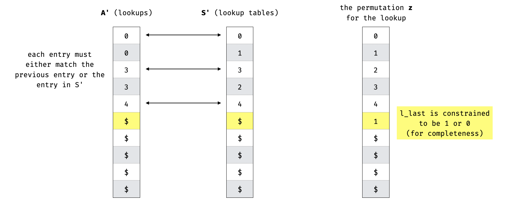
The blinding of these columns is implemented in src/plonk/lookup/prover.rs:
fn permute_expression_pair<F, CS: PolynomialCommitmentScheme<F>, R: RngCore>(
    pk: &ProvingKey<F, CS>,
    domain: &EvaluationDomain<F>,
    mut rng: R,
    input_expression: &Polynomial<F, LagrangeCoeff>,
    table_expression: &Polynomial<F, LagrangeCoeff>,
) -> Result<ExpressionPair<F>, Error>
where
    F: WithSmallOrderMulGroup<3> + Ord + FromUniformBytes<64>,
{
    let blinding_factors = pk.vk.cs.blinding_factors();
    let usable_rows = pk.vk.n() as usize - (blinding_factors + 1);

    // TRUNCATED...

    permuted_input_expression.extend((0..(blinding_factors + 1)).map(|_| F::random(&mut rng)));
    permuted_table_coeffs.extend((0..(blinding_factors + 1)).map(|_| F::random(&mut rng)));
    assert_eq!(permuted_input_expression.len(), pk.vk.n() as usize);
    assert_eq!(permuted_table_coeffs.len(), pk.vk.n() as usize);

    // TRUNCATED...
}
Quotient polynomials can be seen as separate columns in the protocol that are derived from the witness columns. For this reason, they must also be blinded in order to prevent information leakage.
As pointed out in Zero-Knowledge Is Not Fully Implemented this was not done properly.
In Halo2, when evaluating polynomials over an extended domain to accommodate multiplication gates, the polynomial’s evaluations, initially defined over the original domain, are interpolated into coefficients and then re-evaluated over the extended domain. This would normally be done using a multiplicative subgroup of the extended domain. However, Halo2 instead uses a coset of the extended domain’s multiplicative subgroup to avoid division-by-zero errors.
Halo2 performs operations on polynomials in evaluation form, and to compute the quotient polynomial , it divides the constraint polynomial by the vanishing polynomial :
By definition, the vanishing polynomial evaluates to zero over the original domain, and since the extended domain contains the original domain, this means that when computing the quotient polynomial, division by zero would occur. To prevent this issue, Halo2 uses a coset.
One way to create a coset of a multiplicative subgroup is to multiply each element in the subgroup by a scalar value that is not in the subgroup. If the scalar value is in the subgroup, the new set of values will be the same multiplicative subgroup.
Since Halo2 uses a subgroup of size (i.e., some power of 2) to efficiently perform FFT, one can simply find a subgroup of size that does not divide and use an element of that subgroup as the scalar value.
Specifically, Halo2 uses the generator of a multiplicative subgroup that has size and is composed of the following elements: .
Thus, given a multiplicative subgroup of size , we can create a coset by multiplying each element in by :
When evaluating the polynomials over the given coset, Halo2 uses a slight modification to apply the standard FFT algorithm, which expects to evaluate over a multiplicative subgroup, not a coset.
Specifically, instead of multiplying all the evaluation points by , Halo2 multiplies the coefficients of the polynomial by and then performs FFT over the multiplicative subgroup.
For example, suppose we have a polynomial:
and we want to evaluate it over the coset . We get:
which simplifies to:
Since and , we can substitute the powers of :
assuming .
We can also group the coefficients with the powers of so that we can express as:
which means we can multiply each coefficient by one of , then perform FFT over the multiplicative subgroup to obtain the same result as evaluating over .
Below are listed the findings found during the engagement. High severity findings can be seen as
so-called
"priority 0" issues that need fixing (potentially urgently). Medium severity findings are most often
serious
findings that have less impact (or are harder to exploit) than high-severity findings. Low severity
findings
are most often exploitable in contrived scenarios, if at all, but still warrant reflection. Findings
marked
as informational are general comments that did not fit any of the other criteria.